ASME B16.5 · B16.47 · JIS B2220 · EN 1092-1
Slip-On Flange Manufacturer — ASME B16.5, EN 1092-1, JIS B2220
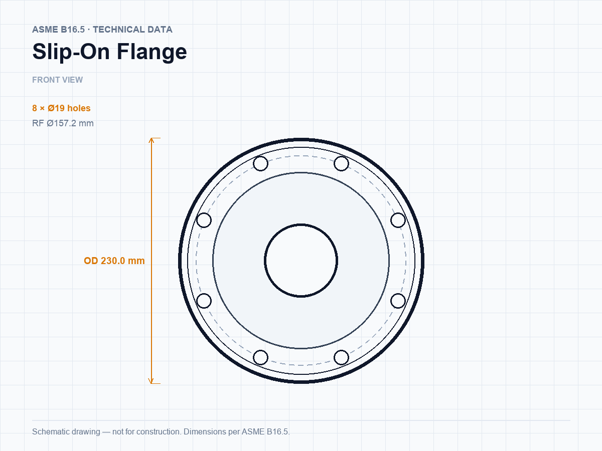
Slip-on flanges slide over the pipe and are fillet-welded on both sides. They are the most economical B16.5 flange for low-pressure, low-temperature lines where alignment matters more than fatigue life.
Standard
ASME B16.5 / EN 1092-1 / JIS B2220
Size range
1/2″–24″ · DN10–DN600 · 10A–600A
Pressure class
Class 150–2500 · PN6–PN40 · 5K–30K
Materials
A105, A350 LF2, 304/316L, F11/F22
Faces
RF, FF
Weld
Fillet weld, both sides
A slip-on flange (SO) is positioned by sliding the bore over the pipe until the hub face sits at the correct stand-out, then welded with a fillet on both the inside and outside. The double fillet gives a robust joint and the generous bore makes field alignment simple, which is why slip-on flanges dominate utility water, HVAC, fire protection and low-pressure process lines.
The trade-off is mechanical: the pipe does not pass through a tapered hub, so the flange is weaker in fatigue and cannot be radiographed like a butt weld. We therefore recommend slip-on flanges for Class 150 and 300 service at moderate temperature, and weld neck flanges for cyclic, high-pressure or severe-service duties. Slip-on flanges are machined to B16.5 in A105, A350 LF2, 304/304L, 316/316L and F11/F22, with RF or FF faces and a 125–250 AARH finish.
Dimensions by standard — ASME, JIS and EN
Each table is the published dimension record for one standard and rating. ASME values are shown in millimetres with the inch equivalent; JIS B2220 and EN 1092-1 values are metric as published. Flange thickness excludes the raised-face height (1.5 mm for ASME B16.5 Classes 150/300, 6.4 mm for Classes 400–2500, 1.5 mm for B16.47 Classes 75/150/300 and 6.4 mm for Classes 400–900, 2 mm for JIS/EN). A size link opens the full specification page for that size and rating.
ASME B16.5
ASME B16.5-2025 · North America, Middle East, South-East Asia
slip-on flange · Class 150
| Size | DN | OD | Thickness | RF Ø | Bolt circle | Bolts | Hub Ø | Length | Weight | |
|---|---|---|---|---|---|---|---|---|---|---|
| 1/2″ | 15 | 88.9 mm (3.5″) | 9.7 mm (0.38″) | 35.1 mm (1.38″) | 60.5 mm (2.38″) | 4 × Ø15.9 mm (0.63″) | 30.2 mm (1.19″) | 14.2 mm (0.56″) | 0.5 kg | Details → |
| 3/4″ | 20 | 98.6 mm (3.88″) | 11.2 mm (0.44″) | 42.9 mm (1.69″) | 69.9 mm (2.75″) | 4 × Ø15.9 mm (0.63″) | 38.1 mm (1.5″) | 14.2 mm (0.56″) | 0.9 kg | Details → |
| 1″ | 25 | 108 mm (4.25″) | 12.7 mm (0.5″) | 50.8 mm (2″) | 79.2 mm (3.12″) | 4 × Ø15.9 mm (0.63″) | 49.3 mm (1.94″) | 15.7 mm (0.62″) | 0.9 kg | Details → |
| 1¼″ | 32 | 117.3 mm (4.62″) | 14.2 mm (0.56″) | 63.5 mm (2.5″) | 88.9 mm (3.5″) | 4 × Ø15.9 mm (0.63″) | 58.7 mm (2.31″) | 19.1 mm (0.75″) | 1.4 kg | Details → |
| 1½″ | 40 | 127 mm (5″) | 15.7 mm (0.62″) | 73.2 mm (2.88″) | 98.6 mm (3.88″) | 4 × Ø15.9 mm (0.63″) | 65 mm (2.56″) | 20.6 mm (0.81″) | 1.4 kg | Details → |
| 2″ | 50 | 152.4 mm (6″) | 17.5 mm (0.69″) | 91.9 mm (3.62″) | 120.7 mm (4.75″) | 4 × Ø19.1 mm (0.75″) | 77.7 mm (3.06″) | 23.9 mm (0.94″) | 2.3 kg | Details → |
| 2½″ | 65 | 177.8 mm (7″) | 20.6 mm (0.81″) | 104.6 mm (4.12″) | 139.7 mm (5.5″) | 4 × Ø19.1 mm (0.75″) | 90.4 mm (3.56″) | 26.9 mm (1.06″) | 3.2 kg | Details → |
| 3″ | 80 | 190.5 mm (7.5″) | 22.4 mm (0.88″) | 127 mm (5″) | 152.4 mm (6″) | 4 × Ø19.1 mm (0.75″) | 108 mm (4.25″) | 28.4 mm (1.12″) | 3.6 kg | Details → |
| 3½″ | 90 | 215.9 mm (8.5″) | 22.4 mm (0.88″) | 139.7 mm (5.5″) | 177.8 mm (7″) | 8 × Ø19.1 mm (0.75″) | 122.2 mm (4.81″) | 30.2 mm (1.19″) | 5 kg | Details → |
| 4″ | 100 | 228.6 mm (9″) | 22.4 mm (0.88″) | 157.2 mm (6.19″) | 190.5 mm (7.5″) | 8 × Ø19.1 mm (0.75″) | 134.9 mm (5.31″) | 31.8 mm (1.25″) | 5.9 kg | Details → |
| 5″ | 125 | 254 mm (10″) | 22.4 mm (0.88″) | 185.7 mm (7.31″) | 215.9 mm (8.5″) | 8 × Ø22.2 mm (0.87″) | 163.6 mm (6.44″) | 35.1 mm (1.38″) | 6.8 kg | Details → |
| 6″ | 150 | 279.4 mm (11″) | 23.9 mm (0.94″) | 215.9 mm (8.5″) | 241.3 mm (9.5″) | 8 × Ø22.2 mm (0.87″) | 192 mm (7.56″) | 38.1 mm (1.5″) | 8.6 kg | Details → |
| 8″ | 200 | 342.9 mm (13.5″) | 26.9 mm (1.06″) | 269.7 mm (10.62″) | 298.5 mm (11.75″) | 8 × Ø22.2 mm (0.87″) | 246.1 mm (9.69″) | 42.9 mm (1.69″) | 13.6 kg | Details → |
| 10″ | 250 | 406.4 mm (16″) | 28.4 mm (1.12″) | 323.9 mm (12.75″) | 362 mm (14.25″) | 12 × Ø25.4 mm (1″) | 304.8 mm (12″) | 47.8 mm (1.88″) | 19.5 kg | Details → |
| 12″ | 300 | 482.6 mm (19″) | 30.2 mm (1.19″) | 381 mm (15″) | 431.8 mm (17″) | 12 × Ø25.4 mm (1″) | 365.3 mm (14.38″) | 53.8 mm (2.12″) | 29 kg | Details → |
| 14″ | 350 | 533.4 mm (21″) | 33.3 mm (1.31″) | 412.8 mm (16.25″) | 476.3 mm (18.75″) | 12 × Ø28.6 mm (1.13″) | 400.1 mm (15.75″) | 55.6 mm (2.19″) | 40.8 kg | Details → |
| 16″ | 400 | 596.9 mm (23.5″) | 35.1 mm (1.38″) | 469.9 mm (18.5″) | 539.8 mm (21.25″) | 16 × Ø28.6 mm (1.13″) | 457.2 mm (18″) | 62 mm (2.44″) | 44.5 kg | Details → |
| 18″ | 450 | 635 mm (25″) | 38.1 mm (1.5″) | 533.4 mm (21″) | 577.9 mm (22.75″) | 16 × Ø31.8 mm (1.25″) | 505 mm (19.88″) | 66.5 mm (2.62″) | 59 kg | Details → |
| 20″ | 500 | 698.5 mm (27.5″) | 41.1 mm (1.62″) | 584.2 mm (23″) | 635 mm (25″) | 20 × Ø31.8 mm (1.25″) | 558.8 mm (22″) | 71.4 mm (2.81″) | 74.8 kg | Details → |
| 22″ | 550 | 749.3 mm (29.5″) | 44.5 mm (1.75″) | 641.4 mm (25.25″) | 692.2 mm (27.25″) | 20 × Ø28.6 mm (1.13″) | 609.6 mm (24″) | 77.7 mm (3.06″) | — | Details → |
| 24″ | 600 | 812.8 mm (32″) | 46 mm (1.81″) | 692.2 mm (27.25″) | 749.3 mm (29.5″) | 20 × Ø34.9 mm (1.37″) | 663.4 mm (26.12″) | 81 mm (3.19″) | 99.8 kg | Details → |
slip-on flange · Class 300
| Size | DN | OD | Thickness | RF Ø | Bolt circle | Bolts | Hub Ø | Length | Weight | |
|---|---|---|---|---|---|---|---|---|---|---|
| 1/2″ | 15 | 95.3 mm (3.75″) | 12.7 mm (0.5″) | 35.1 mm (1.38″) | 66.5 mm (2.62″) | 4 × Ø15.9 mm (0.63″) | 38.1 mm (1.5″) | 20.6 mm (0.81″) | 0.9 kg | Details → |
| 3/4″ | 20 | 117.3 mm (4.62″) | 14.2 mm (0.56″) | 42.9 mm (1.69″) | 82.6 mm (3.25″) | 4 × Ø19.1 mm (0.75″) | 47.8 mm (1.88″) | 23.9 mm (0.94″) | 1.4 kg | Details → |
| 1″ | 25 | 124 mm (4.88″) | 15.7 mm (0.62″) | 50.8 mm (2″) | 88.9 mm (3.5″) | 4 × Ø19.1 mm (0.75″) | 53.8 mm (2.12″) | 25.4 mm (1″) | 1.4 kg | Details → |
| 1¼″ | 32 | 133.4 mm (5.25″) | 17.5 mm (0.69″) | 63.5 mm (2.5″) | 98.6 mm (3.88″) | 4 × Ø19.1 mm (0.75″) | 63.5 mm (2.5″) | 25.4 mm (1″) | 1.8 kg | Details → |
| 1½″ | 40 | 155.4 mm (6.12″) | 19.1 mm (0.75″) | 73.2 mm (2.88″) | 114.3 mm (4.5″) | 4 × Ø22.2 mm (0.87″) | 69.9 mm (2.75″) | 28.7 mm (1.13″) | 2.7 kg | Details → |
| 2″ | 50 | 165.1 mm (6.5″) | 20.6 mm (0.81″) | 91.9 mm (3.62″) | 127 mm (5″) | 8 × Ø19.1 mm (0.75″) | 84.1 mm (3.31″) | 31.8 mm (1.25″) | 3.2 kg | Details → |
| 2½″ | 65 | 190.5 mm (7.5″) | 23.9 mm (0.94″) | 104.6 mm (4.12″) | 149.4 mm (5.88″) | 8 × Ø22.2 mm (0.87″) | 100.1 mm (3.94″) | 36.6 mm (1.44″) | 4.5 kg | Details → |
| 3″ | 80 | 209.6 mm (8.25″) | 26.9 mm (1.06″) | 127 mm (5″) | 168.1 mm (6.62″) | 8 × Ø22.2 mm (0.87″) | 117.3 mm (4.62″) | 41.4 mm (1.63″) | 5.9 kg | Details → |
| 3½″ | 90 | 228.6 mm (9″) | 28.4 mm (1.12″) | 139.7 mm (5.5″) | 184.2 mm (7.25″) | 8 × Ø22.2 mm (0.87″) | 133.4 mm (5.25″) | 42.9 mm (1.69″) | 7.7 kg | Details → |
| 4″ | 100 | 254 mm (10″) | 30.2 mm (1.19″) | 157.2 mm (6.19″) | 200.2 mm (7.88″) | 8 × Ø22.2 mm (0.87″) | 146.1 mm (5.75″) | 46.2 mm (1.82″) | 10 kg | Details → |
| 5″ | 125 | 279.4 mm (11″) | 33.3 mm (1.31″) | 185.7 mm (7.31″) | 235 mm (9.25″) | 8 × Ø22.2 mm (0.87″) | 177.8 mm (7″) | 49.3 mm (1.94″) | 12.7 kg | Details → |
| 6″ | 150 | 317.5 mm (12.5″) | 35.1 mm (1.38″) | 215.9 mm (8.5″) | 269.7 mm (10.62″) | 12 × Ø22.2 mm (0.87″) | 206.2 mm (8.12″) | 50.8 mm (2″) | 17.7 kg | Details → |
| 8″ | 200 | 381 mm (15″) | 39.6 mm (1.56″) | 269.7 mm (10.62″) | 330.2 mm (13″) | 12 × Ø25.4 mm (1″) | 260.4 mm (10.25″) | 60.5 mm (2.38″) | 26.3 kg | Details → |
| 10″ | 250 | 444.5 mm (17.5″) | 46 mm (1.81″) | 323.9 mm (12.75″) | 387.4 mm (15.25″) | 16 × Ø28.6 mm (1.13″) | 320.5 mm (12.62″) | 65 mm (2.56″) | 36.7 kg | Details → |
| 12″ | 300 | 520.7 mm (20.5″) | 49.3 mm (1.94″) | 381 mm (15″) | 450.9 mm (17.75″) | 16 × Ø31.8 mm (1.25″) | 374.7 mm (14.75″) | 71.6 mm (2.82″) | 52.2 kg | Details → |
| 14″ | 350 | 584.2 mm (23″) | 52.3 mm (2.06″) | 412.8 mm (16.25″) | 514.4 mm (20.25″) | 20 × Ø31.8 mm (1.25″) | 425.5 mm (16.75″) | 74.7 mm (2.94″) | 74.8 kg | Details → |
| 16″ | 400 | 647.7 mm (25.5″) | 55.6 mm (2.19″) | 469.9 mm (18.5″) | 571.5 mm (22.5″) | 20 × Ø34.9 mm (1.37″) | 482.6 mm (19″) | 81 mm (3.19″) | 86.2 kg | Details → |
| 18″ | 450 | 711.2 mm (28″) | 58.7 mm (2.31″) | 533.4 mm (21″) | 628.7 mm (24.75″) | 24 × Ø34.9 mm (1.37″) | 533.4 mm (21″) | 87.4 mm (3.44″) | 113 kg | Details → |
| 20″ | 500 | 774.7 mm (30.5″) | 62 mm (2.44″) | 584.2 mm (23″) | 685.8 mm (27″) | 24 × Ø34.9 mm (1.37″) | 587.2 mm (23.12″) | 93.7 mm (3.69″) | 143 kg | Details → |
| 22″ | 550 | 838.2 mm (33″) | 65 mm (2.56″) | 641.4 mm (25.25″) | 743 mm (29.25″) | 24 × Ø41.3 mm (1.63″) | 641.4 mm (25.25″) | 100.1 mm (3.94″) | — | Details → |
| 24″ | 600 | 914.4 mm (36″) | 68.3 mm (2.69″) | 692.2 mm (27.25″) | 812.8 mm (32″) | 24 × Ø41.3 mm (1.63″) | 701.5 mm (27.62″) | 104.9 mm (4.13″) | 215 kg | Details → |
JIS B2220
JIS B2220:2012 · Japan, Korea, South-East Asia, marine and shipbuilding
slip-on flange · 10K
| Size | DN | OD | Thickness | RF Ø | Bolt circle | Bolts | Weight | |
|---|---|---|---|---|---|---|---|---|
| 10A | 10 | 90 mm | 12 mm | 46 mm | 65 mm | 4 × Ø15 mm | 0.51 kg | Details → |
| 15A | 15 | 95 mm | 12 mm | 51 mm | 70 mm | 4 × Ø15 mm | 0.56 kg | Details → |
| 20A | 20 | 100 mm | 14 mm | 56 mm | 75 mm | 4 × Ø15 mm | 0.72 kg | Details → |
| 25A | 25 | 125 mm | 14 mm | 67 mm | 90 mm | 4 × Ø19 mm | 1.12 kg | Details → |
| 32A | 32 | 135 mm | 16 mm | 76 mm | 100 mm | 4 × Ø19 mm | 1.47 kg | Details → |
| 40A | 40 | 140 mm | 16 mm | 81 mm | 105 mm | 4 × Ø19 mm | 1.55 kg | Details → |
| 50A | 50 | 155 mm | 16 mm | 96 mm | 120 mm | 4 × Ø19 mm | 1.86 kg | Details → |
| 65A | 65 | 175 mm | 18 mm | 116 mm | 140 mm | 4 × Ø19 mm | 2.58 kg | Details → |
| 80A | 80 | 185 mm | 18 mm | 126 mm | 150 mm | 8 × Ø19 mm | 2.64 kg | Details → |
| 90A | 90 | 195 mm | 18 mm | 136 mm | 160 mm | 8 × Ø19 mm | 2.73 kg | Details → |
| 100A | 100 | 210 mm | 18 mm | 151 mm | 175 mm | 8 × Ø19 mm | 3.1 kg | Details → |
| 125A | 125 | 250 mm | 20 mm | 182 mm | 210 mm | 8 × Ø23 mm | 4.73 kg | Details → |
| 150A | 150 | 280 mm | 22 mm | 212 mm | 240 mm | 8 × Ø23 mm | 6.3 kg | Details → |
| 175A | 175 | 305 mm | 22 mm | 237 mm | 265 mm | 12 × Ø23 mm | 6.75 kg | Details → |
| 200A | 200 | 330 mm | 22 mm | 262 mm | 290 mm | 12 × Ø23 mm | 7.46 kg | Details → |
| 225A | 225 | 350 mm | 22 mm | 282 mm | 310 mm | 12 × Ø23 mm | 7.7 kg | Details → |
| 250A | 250 | 400 mm | 24 mm | 324 mm | 355 mm | 12 × Ø25 mm | 11.8 kg | Details → |
| 300A | 300 | 445 mm | 24 mm | 368 mm | 400 mm | 16 × Ø25 mm | 12.6 kg | Details → |
| 350A | 350 | 490 mm | 26 mm | 413 mm | 445 mm | 16 × Ø25 mm | 16.3 kg | Details → |
| 400A | 400 | 560 mm | 28 mm | 475 mm | 510 mm | 16 × Ø27 mm | 23.2 kg | Details → |
| 450A | 450 | 620 mm | 30 mm | 530 mm | 565 mm | 20 × Ø27 mm | 29.3 kg | Details → |
| 500A | 500 | 675 mm | 30 mm | 585 mm | 620 mm | 20 × Ø27 mm | 33.3 kg | Details → |
| 550A | 550 | 745 mm | 32 mm | 640 mm | 680 mm | 20 × Ø33 mm | 42.9 kg | Details → |
| 600A | 600 | 795 mm | 32 mm | 690 mm | 730 mm | 24 × Ø33 mm | 45.4 kg | Details → |
EN 1092-1
EN 1092-1:2018 · Europe, UK, Middle East, Africa, CIS projects
slip-on flange · PN16
| Size | DN | OD | Thickness | RF Ø | Bolt circle | Bolts | Hub Ø | Length | |
|---|---|---|---|---|---|---|---|---|---|
| DN10 | 10 | 90 mm | 16 mm | 40 mm | 60 mm | 4 × Ø14 mm | 30 mm | 22 mm | Details → |
| DN15 | 15 | 95 mm | 16 mm | 45 mm | 65 mm | 4 × Ø14 mm | 35 mm | 22 mm | Details → |
| DN20 | 20 | 105 mm | 18 mm | 58 mm | 75 mm | 4 × Ø14 mm | 45 mm | 26 mm | Details → |
| DN25 | 25 | 115 mm | 18 mm | 68 mm | 85 mm | 4 × Ø14 mm | 52 mm | 28 mm | Details → |
| DN32 | 32 | 140 mm | 18 mm | 78 mm | 100 mm | 4 × Ø18 mm | 60 mm | 30 mm | Details → |
| DN40 | 40 | 150 mm | 18 mm | 88 mm | 110 mm | 4 × Ø18 mm | 70 mm | 32 mm | Details → |
| DN50 | 50 | 165 mm | 18 mm | 102 mm | 125 mm | 4 × Ø18 mm | 84 mm | 28 mm | Details → |
| DN65 | 65 | 185 mm | 18 mm | 122 mm | 145 mm | 8 × Ø18 mm | 104 mm | 32 mm | Details → |
| DN80 | 80 | 200 mm | 20 mm | 138 mm | 160 mm | 8 × Ø18 mm | 118 mm | 34 mm | Details → |
| DN100 | 100 | 220 mm | 20 mm | 158 mm | 180 mm | 8 × Ø18 mm | 140 mm | 40 mm | Details → |
| DN125 | 125 | 250 mm | 22 mm | 188 mm | 210 mm | 8 × Ø18 mm | 168 mm | 44 mm | Details → |
| DN150 | 150 | 285 mm | 22 mm | 212 mm | 240 mm | 8 × Ø22 mm | 195 mm | 44 mm | Details → |
| DN200 | 200 | 340 mm | 24 mm | 268 mm | 295 mm | 12 × Ø22 mm | 246 mm | 44 mm | Details → |
| DN250 | 250 | 405 mm | 26 mm | 320 mm | 355 mm | 12 × Ø26 mm | 298 mm | 46 mm | Details → |
| DN300 | 300 | 460 mm | 28 mm | 378 mm | 410 mm | 12 × Ø26 mm | 350 mm | 46 mm | Details → |
| DN350 | 350 | 520 mm | 30 mm | 438 mm | 470 mm | 16 × Ø26 mm | 400 mm | 57 mm | Details → |
| DN400 | 400 | 580 mm | 32 mm | 490 mm | 525 mm | 16 × Ø30 mm | 456 mm | 63 mm | Details → |
| DN450 | 450 | 640 mm | 34 mm | 550 mm | 585 mm | 20 × Ø30 mm | 502 mm | 68 mm | Details → |
| DN500 | 500 | 715 mm | 36 mm | 610 mm | 650 mm | 20 × Ø33 mm | 559 mm | 73 mm | Details → |
| DN600 | 600 | 840 mm | 40 mm | 725 mm | 770 mm | 20 × Ø36 mm | 658 mm | 83 mm | Details → |
Full rating sets are published on the standard pages: B16.5 · B16.47 A · B16.47 B · JIS B2220 · EN 1092-1 . Tables are compiled from published ASME B16.5-2025, JIS B2220:2012, EN 1092-1:2018 data — verify against the edition named in your purchase specification before quoting a critical part.
Key features
Easy field alignment
The clearance bore lets the flange be rotated and positioned on the pipe before welding, which reduces fit-up time on site and in fabrication shops.
Lower unit cost
Less material and simpler machining than a weld neck flange — the right choice when the line is not fatigue- or pressure-critical.
Both-side fillet weld
The hub is machined with a defined stand-out so the welder can run a consistent fillet inside and outside without burning through the pipe wall.
Standard and custom bores
Bores are machined to the mating pipe OD; for thin-wall or lined pipe we adjust the bore and hub to keep the weld sound.
Typical applications
- Utility water, cooling water and fire-protection lines
- HVAC and building services piping
- Low-pressure chemical and food-grade lines
- Compressed air and inert gas distribution
- Tank and vessel connections
- Retrofit and maintenance work where alignment is difficult
Quality control & documentation
- Dimensional inspection to B16.5 tables, recorded per lot
- Visual and PMI check on stainless and alloy heats
- MTC 3.1 per heat with chemical and mechanical results
- Face flatness and surface finish checked before packing
Material certificates to EN 10204 3.1 are issued with every shipment; third-party inspection (SGS, BV, TÜV) can be arranged on request.
Frequently asked questions
Where should a slip-on flange not be used?
Avoid slip-on flanges in cyclic or high-pressure service, in lines that will be radiographed, and where crevice corrosion is a risk — the gap between pipe and bore can trap process fluid. Use weld neck flanges in those cases.
How far should the pipe sit inside the flange?
Set the pipe end flush with the flange face minus the weld preparation, so the pipe does not protrude into the gasket area. We can mark the stand-out on the hub on request.
Do you supply slip-on flanges to DIN or EN?
Yes — EN 1092-1 type 12/13 and JIS B2220 SOP slip-on flanges are available alongside ASME B16.5, and the older DIN 2632 dimensions still match in most sizes. Send the standard and pressure rating (PN, K or class) and we will confirm dimensions.
Request a quotation
Send your slip-on flange specification
Include the standard, size, pressure class, material, face type and quantity. Drawings are welcome — we will confirm feasibility, lead time and price within one business day.
- ★ Reply within 24 hours on business days
- ★ MTC 3.1 and dimensional report with every order
- ★ FOB, CIF and DDP terms available
Send an Inquiry
Send drawings, dimensions or a standard reference. Our sales engineers reply within 24 hours on business days.