ASME B16.47 Series B · ASTM A105 · stock and made to order
38″ Class 400 Weld Neck Flange — ASME B16.47 Series B
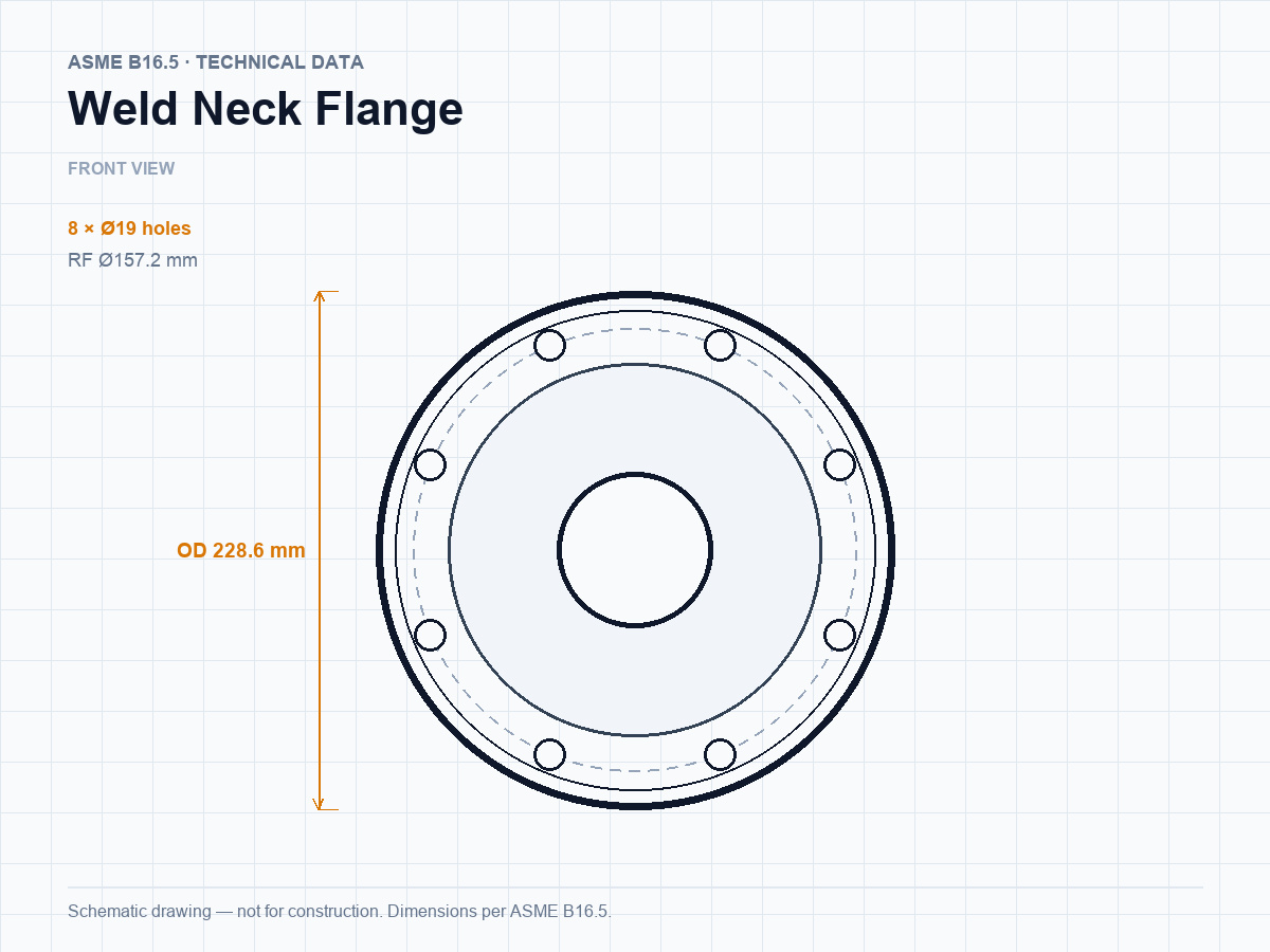
38″ Class 400 weld neck flange to ASME B16.47 Series B, machined from ASTM A105. Outside diameter 1206 mm, thickness 124 mm, 32 bolt holes on a 1117.6 mm circle. Available with raised face, flat face or the facing specified on your drawing.
Size
38″ / DN950
Standard
ASME B16.47 Series B (ASME B16.47-2025, Series B)
Pressure rating
Class 400
Outside diameter
1206 mm (47.48″)
Thickness
124 mm (4.88″)
Bolt circle
1117.6 mm (44″)
Full dimensions — 38″ Class 400
| Size | DN | OD | Thickness | RF Ø | Bolt circle | Bolts | Hub Ø | Length | Weight | |
|---|---|---|---|---|---|---|---|---|---|---|
| 26″ | 650 | 851 mm (33.5″) | 88.9 mm (3.5″) | 711 mm (27.99″) | 781 mm (30.75″) | 28 × Ø38.1 mm (1.5″) | 689 mm (27.13″) | 149 mm (5.87″) | 163 kg | Details → |
| 28″ | 700 | 914 mm (35.98″) | 95.3 mm (3.75″) | 762 mm (30″) | 838.2 mm (33″) | 24 × Ø41.3 mm (1.63″) | 740 mm (29.13″) | 159 mm (6.26″) | 204 kg | Details → |
| 30″ | 750 | 972 mm (38.27″) | 101.6 mm (4″) | 819 mm (32.24″) | 895.4 mm (35.25″) | 28 × Ø41.3 mm (1.63″) | 794 mm (31.26″) | 170 mm (6.69″) | 240 kg | Details → |
| 32″ | 800 | 1035 mm (40.75″) | 108 mm (4.25″) | 873 mm (34.37″) | 952.5 mm (37.5″) | 28 × Ø44.5 mm (1.75″) | 845 mm (33.27″) | 179 mm (7.05″) | 288 kg | Details → |
| 34″ | 850 | 1086 mm (42.76″) | 111.3 mm (4.38″) | 927 mm (36.5″) | 1003.3 mm (39.5″) | 32 × Ø44.5 mm (1.75″) | 899 mm (35.39″) | 187 mm (7.36″) | 313 kg | Details → |
| 36″ | 900 | 1156 mm (45.51″) | 119.1 mm (4.69″) | 981 mm (38.62″) | 1066.8 mm (42″) | 28 × Ø47.6 mm (1.87″) | 952 mm (37.48″) | 200 mm (7.87″) | 388 kg | Details → |
| 38″ (this size) | 950 | 1206 mm (47.48″) | 124 mm (4.88″) | 1035 mm (40.75″) | 1117.6 mm (44″) | 32 × Ø47.6 mm (1.87″) | 1003 mm (39.49″) | 206 mm (8.11″) | — | Details → |
| 40″ | 1000 | 1270 mm (50″) | 130 mm (5.12″) | 1092 mm (42.99″) | 1174.8 mm (46.25″) | 32 × Ø50.8 mm (2″) | 1054 mm (41.5″) | 216 mm (8.5″) | — | Details → |
| 42″ | 1050 | 1321 mm (52.01″) | 133.4 mm (5.25″) | 1143 mm (45″) | 1225.6 mm (48.25″) | 32 × Ø50.8 mm (2″) | 1108 mm (43.62″) | 224 mm (8.82″) | — | Details → |
| 44″ | 1100 | 1384 mm (54.49″) | 139.7 mm (5.5″) | 1200 mm (47.24″) | 1282.7 mm (50.5″) | 32 × Ø54 mm (2.13″) | 1159 mm (45.63″) | 233 mm (9.17″) | — | Details → |
| 46″ | 1150 | 1441 mm (56.73″) | 146.1 mm (5.75″) | 1257 mm (49.49″) | 1339.8 mm (52.75″) | 36 × Ø54 mm (2.13″) | 1213 mm (47.76″) | 244 mm (9.61″) | — | Details → |
| 48″ | 1200 | 1511 mm (59.49″) | 152.4 mm (6″) | 1308 mm (51.5″) | 1403.4 mm (55.25″) | 28 × Ø60.3 mm (2.37″) | 1267 mm (49.88″) | 257 mm (10.12″) | — | Details → |
| 50″ | 1250 | 1568 mm (61.73″) | 157.2 mm (6.19″) | 1362 mm (53.62″) | 1460.5 mm (57.5″) | 32 × Ø60.3 mm (2.37″) | 1321 mm (52.01″) | 268 mm (10.55″) | — | Details → |
| 52″ | 1300 | 1619 mm (63.74″) | 162.1 mm (6.38″) | 1413 mm (55.63″) | 1511.3 mm (59.5″) | 32 × Ø60.3 mm (2.37″) | 1372 mm (54.02″) | 276 mm (10.87″) | — | Details → |
| 54″ | 1350 | 1702 mm (67.01″) | 169.9 mm (6.69″) | 1470 mm (57.87″) | 1581.2 mm (62.25″) | 28 × Ø66.7 mm (2.63″) | 1425 mm (56.1″) | 289 mm (11.38″) | — | Details → |
| 56″ | 1400 | 1753 mm (69.02″) | 174.8 mm (6.88″) | 1527 mm (60.12″) | 1632 mm (64.25″) | 32 × Ø66.7 mm (2.63″) | 1480 mm (58.27″) | 298 mm (11.73″) | — | Details → |
| 58″ | 1450 | 1803 mm (70.98″) | 177.8 mm (7″) | 1578 mm (62.13″) | 1682.8 mm (66.25″) | 32 × Ø66.7 mm (2.63″) | 1530 mm (60.24″) | 306 mm (12.05″) | — | Details → |
| 60″ | 1500 | 1886 mm (74.25″) | 185.7 mm (7.31″) | 1635 mm (64.37″) | 1752.6 mm (69″) | 32 × Ø73 mm (2.87″) | 1584 mm (62.36″) | 319 mm (12.56″) | — | Details → |
Published ASME B16.47 Series B dimensions for every Class 400 size in this product family.
Dimensions in millimetres; the inch equivalent is shown in brackets. Bolt hole diameter applies to through-holes. For stud length, gasket and bolting selection, match the gasket and bolts to B16.47 B.
What Class 400 means in service
Series B follows the former API 605 dimensions, with a smaller outside diameter and a different bolt pattern from Series A. Ratings are ASME classes 150, 300, 400, 600 and 900, with allowable pressure from the B16.47 tables.
Series B follows the former API 605 dimensions, with a smaller outside diameter and a different bolt pattern from Series A. Ratings are ASME classes 150, 300, 400, 600 and 900, with allowable pressure from the B16.47 tables.
Facing and materials
Raised face (RF) is standard: 1.5 mm high for Classes 75, 150 and 300; 6.4 mm for Classes 400, 600 and 900. FF and RTJ faces are available to drawing.
- ASTM A105 / A105N
- ASTM A350 LF2
- ASTM A182 F304/F316L
- ASTM A694 F52/F60/F65
- ASTM A182 F51/F53
Other grades, impact-tested heats and NACE MR0175 requirements are quoted on request. Material certificates to EN 10204 3.1 are issued against the same heat number as the dimensional report.
Inspection and delivery
- Dimensional inspection against the B16.47 B table for 38″ Class 400
- Heat number stamped on the rim; EN 10204 3.1 certificate issued
- PMI on stainless and alloy heats; UT/RT on request
- Anti-rust oil, plywood case or pallet, with packing list and MTC
- Typical lead time 7–15 days for carbon steel stock sizes, 20–30 days for alloys
Other sizes in Class 400
Request a quotation
38″ Class 400 Weld Neck Flange
Tell us the quantity, face type, material and delivery port. We will confirm price, lead time and the applicable certificate within one business day.
Send an Inquiry
Send drawings, dimensions or a standard reference. Our sales engineers reply within 24 hours on business days.